Thread Rating:
  • 21 Vote(s) - 2.19 Average
  • 1
  • 2
  • 3
  • 4
  • 5
MC424 install WI-FI Switch
#1
Hello,
I recently bought a wi-fi switch and I want to install it in my MC424 unit. The job seems straight forward but I need a confirmation so I dont damage my unit Smile.

This is the switch:
   

This is how I would connect it to my unit:
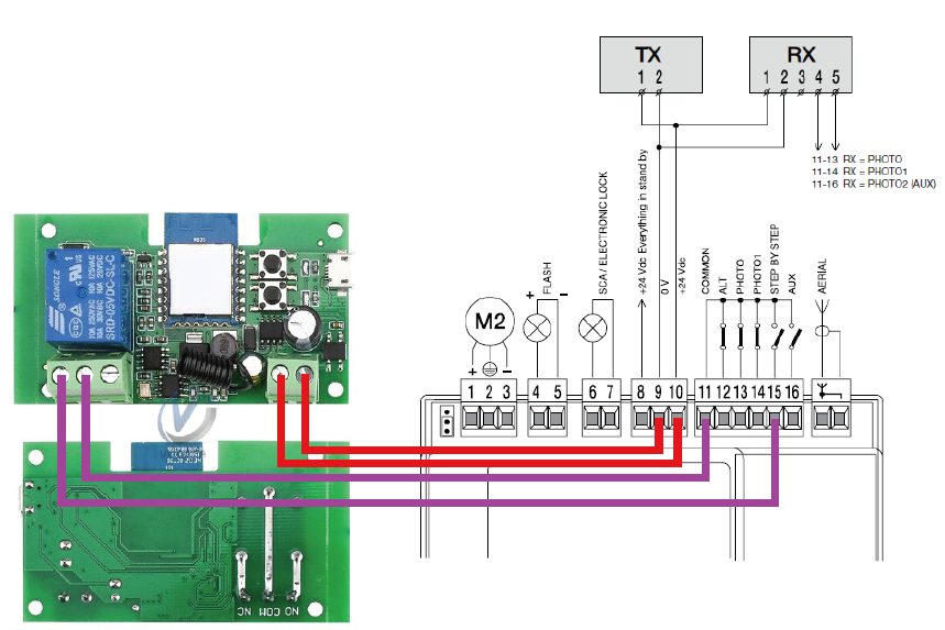
   

I will check the switch so it does not have voltage on the pins I would connect into pins 11 (common) and Pin 15(step by step).

I imagine when I switch on, the gates will close/open and when I switch off, they would close/open, depending on the state they were in initially. 

So is this correct, should I proceed? Thank you for your time.

Edit: This is how my unit looks like now:
   
Reply
#2
Hi,

I hope you are well. This idea looks acceptable. You will need to ensure that the switch is in fact a dry contact (which you believe it is). If so, this will work. For example, if your gates are in the closed position and you switch on an open command will be sent to the SBS opening the gate. You will then have to switch off, on, to send a close command to the SBS.

Regards,
-Jamie
Gate Automation and Access Control from EasyGates Retail Store

EasyGates Trade Store for Trade only

Smart Home Tech from The Smart and Secure Centre

Smart Home News from Smart Home Matters
Reply
#3
Hi Jamie,
I installed the switch and it works perfectly. I forgot to update the thread, good thing you replied Smile.
All I had to do extra is put the switch in inching mode with a 2 sec delay, because by default it was in normal switch operating mode.
Considering they sell these switches extremely cheap this is a very nice addition to my gates.

Cheers,
George
Reply
#4
I am new to the forum.
I have the exact same wifi receiver and I would like to connect it to a Nice Robus 400.
I just don't know what goes where.
Please help


Attached Files Image(s)
   
Reply
#5
(05-07-2021, 07:36 AM)Petersjcage Wrote: I am new to the forum.
I have the exact same wifi receiver and I would like to connect it to a Nice Robus 400.
I just don't know what goes where.
Please help

Hi Peter,

I hope you are well. You will need to take your power from the right side of stop and the left hand side of PP. The right hand side of stop is negative (-) and the left hand side of P.P is positive (+). You will then need to wire into P.P instead of COM and SBS. The polarity of this does not matter, simply wire from the smart switch into the P.P terminal, it is fine to have this and your power wired into the same terminal.

Kind regards
-Jamie
Gate Automation and Access Control from EasyGates Retail Store

EasyGates Trade Store for Trade only

Smart Home Tech from The Smart and Secure Centre

Smart Home News from Smart Home Matters
Reply
#6
(05-07-2021, 12:42 PM)JamieF Wrote:
(05-07-2021, 07:36 AM)Petersjcage Wrote: I am new to the forum.
I have the exact same wifi receiver and I would like to connect it to a Nice Robus 400.
I just don't know what goes where.
Please help

Hi Peter,

I hope you are well. You will need to take your power from the right side of stop and the left hand side of PP. The right hand side of stop is negative (-) and the left hand side of P.P is positive (+). You will then need to wire into P.P instead of COM and SBS. The polarity of this does not matter, simply wire from the smart switch into the P.P terminal, it is fine to have this and your power wired into the same terminal.
Thanks for  this - what voltage should I expect to receive from the right side of stop and the left hand side of PP?  24VDC?
Reply
#7
(04-03-2022, 06:30 AM)psmedley Wrote:
(05-07-2021, 12:42 PM)JamieF Wrote:
(05-07-2021, 07:36 AM)Petersjcage Wrote: I am new to the forum.
I have the exact same wifi receiver and I would like to connect it to a Nice Robus 400.
I just don't know what goes where.
Please help

Hi Peter,

I hope you are well. You will need to take your power from the right side of stop and the left hand side of PP. The right hand side of stop is negative (-) and the left hand side of P.P is positive (+). You will then need to wire into P.P instead of COM and SBS. The polarity of this does not matter, simply wire from the smart switch into the P.P terminal, it is fine to have this and your power wired into the same terminal.
Thanks for  this - what voltage should I expect to receive from the right side of stop and the left hand side of PP?  24VDC?
Hi Peter,

Correct, 24vDC. 

Kind regards
-Jamie
Gate Automation and Access Control from EasyGates Retail Store

EasyGates Trade Store for Trade only

Smart Home Tech from The Smart and Secure Centre

Smart Home News from Smart Home Matters
Reply


Possibly Related Threads…
Thread Author Replies Views Last Post
  MC424 PhotoCell Bypass for Constant Power AdamG 0 514 29-06-2024, 02:45 PM
Last Post: AdamG
  Nice Robus RBA3c Wifi Relay Switch Wiring denis 1 3,917 01-11-2023, 09:45 AM
Last Post: Michael
  Installing Nice photo sensors MC424 polomint 14 48,382 29-03-2021, 06:28 PM
Last Post: pembers
  MC424 - close automatically once open maaarek 3 25,994 03-12-2017, 10:35 AM
Last Post: Automatic-TC
  ORNO Video Doorphone -> NICE MC424 askoba 1 13,701 19-04-2017, 06:52 AM
Last Post: Automatic-TC
  Use MC424 without photocell bullyx 1 16,448 02-08-2015, 03:37 PM
Last Post: jaydev
  Nice MC424 control box interface to intercom access polomint 2 17,588 05-11-2012, 05:36 PM
Last Post: polomint

Forum Jump:


Users browsing this thread: 1 Guest(s)